Digital Display Pressure Transmitter Output Signal Unstable? Troubleshoot from These 4 Directions
In industrial sites, the digital display pressure transmitter is a core device for pressure monitoring. But when the output signal fluctuates, jumps, or drifts, many engineers' first reaction is "the sensor is broken." However, according to over a decade of on-site service experience from Kunlun Zhongda's technical team, more than 60% of signal instability issues are not rooted in the sensor itself.
Signal instability requires troubleshooting the right direction, not simply replacing the product. This article provides a systematic analysis from four dimensions to help you quickly locate the problem and reduce unnecessary downtime losses.
I. Power Supply: The Most Overlooked "Invisible Killer"
The output signal stability of a digital display pressure transmitter first depends on power supply quality.
Typical Symptoms:
-
Signal fluctuates with the start and stop of other equipment
-
Output value periodically jumps, unrelated to actual on-site pressure changes
-
Transmitter shows abnormalities at specific times of the day
Common Causes and Solutions:
Cause: Unstable power supply voltage
-
Symptom: Output signal changes with voltage fluctuation
-
Solution: Check the power module and use a regulated power supply
Cause: Excessive power ripple
-
Symptom: High-frequency noise superimposed on the signal
-
Solution: Add a power filter or replace with a low-ripple power supply
Cause: Insufficient power capacity
-
Symptom: Signal drops when multiple devices run simultaneously
-
Solution: Calculate total load and replace with a power supply of sufficient capacity
Cause: Common ground interference between power supply and transmitter
-
Symptom: Signal affected by ground loop
-
Solution: Use isolated power supply or single-point grounding
Troubleshooting Steps:
-
Measure the transmitter power supply terminal voltage with a multimeter to confirm it is within the rated range (typically 24VDC ±10%)
-
Observe power ripple with an oscilloscope; peak should be less than 100mV
-
Disconnect other loads and check if the signal returns to stability
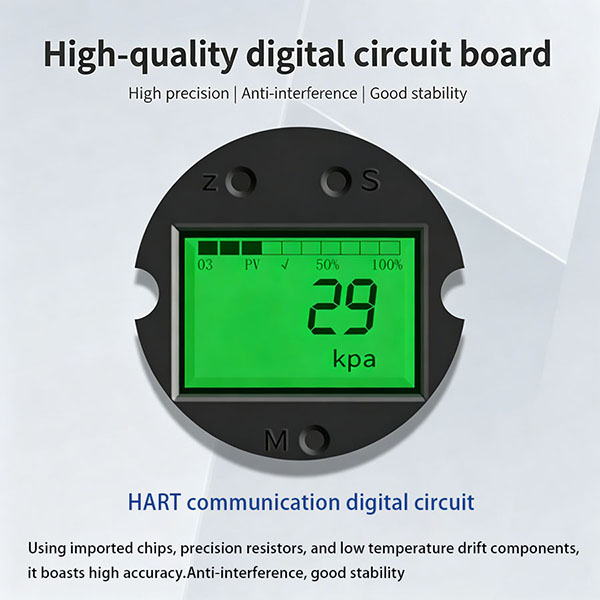
Selection Tip: For applications requiring high stability, choosing a transmitter with built-in voltage regulation and filtering circuits can significantly reduce power interference. This Intelligent explosion-proof high-precision pressure transmitter with display features a comprehensive power management module, performing more reliably in environments with power fluctuations.
II. Installation and Mechanical Connection: Physical Factors Causing Signal Anomalies
Signal instability is not necessarily an electrical issue; sometimes the problem lies in the installation method.
Typical Symptoms:
-
Signal fluctuates with equipment vibration
-
Pressure reading deviates consistently from actual pressure
-
Output signal shows periodic changes synchronized with equipment operation rhythm
Common Causes and Solutions:
Cause: Mismatched installation thread and interface
-
Symptom: Poor sealing, pressure leakage
-
Solution: Confirm thread specifications, use adapter fittings or thread seal tape
Cause: Vibration at installation location
-
Symptom: Internal sensing element disturbed by vibration
-
Solution: Add vibration-damping devices or use flexible hose connections
Cause: Improper pressure tap location
-
Symptom: Measuring dynamic pressure rather than true pressure
-
Solution: Position the pressure tap on a straight pipe section, away from elbows and valves
Cause: Air in the line (for liquid media)
-
Symptom: Significant signal fluctuation
-
Solution: Install an air vent valve before the pressure tap
Troubleshooting Steps:
-
Touch the installation area to feel for obvious vibration
-
Check threaded connections for media leakage
-
Confirm the pressure tap is on a straight pipe section (5D before, 3D after principle)
-
Temporarily change the installation direction or position and observe signal changes
Selection Tip: In applications with significant vibration or limited installation space, this Water Pressure Air Pressure Hydraulic Pressure Universal Pressure Transmitter features a compact structure for flexible installation and excellent vibration resistance.
III. Medium and Operating Conditions: The "Hidden Interference" of the Field Environment
The real challenge for a pressure transmitter in use often comes from the medium itself.
Typical Symptoms:
-
Signal gradually drifts over time
-
Anomalies appear at specific temperature or pressure ranges
-
Intermittent signal interruption or jumping
Common Causes and Solutions:
Cause: Medium temperature exceeds transmitter tolerance
-
Symptom: Zero/span drift
-
Solution: Add heat sinks or select a high-temperature transmitter
Cause: Corrosive medium
-
Symptom: Sensor diaphragm damaged, signal distorted
-
Solution: Replace with corrosion-resistant materials such as Hastelloy or tantalum diaphragm
Cause: Medium contains impurities or crystallizes
-
Symptom: Pressure tap blocked, slow response
-
Solution: Regular cleaning, add filters or isolation diaphragms
Cause: Medium pressure pulsation (e.g., pump outlet)
-
Symptom: Signal follows pulsation fluctuation
-
Solution: Add a snubber or select a transmitter with damping function
Troubleshooting Steps:
-
Measure the actual medium temperature and compare with transmitter specifications
-
Check the pressure tap for crystallization or impurity blockage
-
Observe whether signal fluctuation frequency matches the pump/compressor operating frequency
Selection Tip: This Imported diffused silicon pressure transmitter uses imported diffused silicon chips, offering excellent performance in medium temperature fluctuations and long-term stability, making it suitable for applications with high reliability requirements.
IV. Signal Transmission and Terminal Matching: The Invisible "Last Mile"
Even if the transmitter itself is working properly, problems can occur during signal transmission.
Typical Symptoms:
-
Signal reading at the control end differs from the on-site display value
-
Signal jumps but the transmitter local display is normal
-
Signal quality degrades as transmission distance increases
Common Causes and Solutions:
Cause: Excessive cable length causing signal attenuation
-
Symptom: Remote signal low or fluctuating
-
Solution: Shorten cable length or add a signal amplifier
Cause: Poor shielding layer grounding
-
Symptom: Signal affected by electromagnetic interference
-
Solution: Check that the shielding layer is reliably grounded at one end
Cause: Cable routed in the same conduit as power cables
-
Symptom: Signal interfered with by variable frequency drives and other equipment
-
Solution: Run cables separately with a spacing >30cm
Cause: Mismatched load resistance
-
Symptom: Output current cannot be properly converted
-
Solution: Confirm load resistance is within the transmitter's rated range
Troubleshooting Steps:
-
Measure the signal value at both the transmitter end and the receiving end, and compare for consistency
-
Check that the cable shielding layer is grounded at one end
-
Observe whether signal interference is synchronized with the start/stop of variable frequency drives
V. Troubleshooting Flowchart
A path to quickly locate the root cause of signal instability:
Step 1: Power Supply Check
-
Check items: Voltage instability / Excessive ripple / Insufficient capacity / Common ground interference
-
If normal, proceed to next step. If abnormal, resolve power supply issue.
Step 2: Installation Check
-
Check items: Thread match / Vibration / Pressure tap position / Line venting
-
If normal, proceed to next step. If abnormal, adjust installation method.
Step 3: Medium Check
-
Check items: Temperature / Corrosiveness / Impurities / Pulsation
-
If normal, proceed to next step. If abnormal, select product suitable for the operating conditions.
Step 4: Transmission Check
-
Check items: Signal attenuation / Grounding interference / Shared conduit / Load matching
-
If normal, send to manufacturer for testing/replacement. If abnormal, optimize transmission path.
VI. Selection Recommendations: Preventing Signal Instability at the Source
Rather than troubleshooting after problems occur, it's better to take preventive measures during selection. Here are recommendations for different operating conditions:
Condition: Vibration present, limited installation space
-
Recommended feature: Compact size, vibration-resistant, flexible installation
-
Corresponding product characteristic: Water Pressure Air Pressure Hydraulic Pressure Universal Pressure Transmitter
Condition: Explosion-proof required with on-site data viewing
-
Recommended feature: Explosion-proof certification, local display, high precision
-
Corresponding product characteristic: Intelligent explosion-proof high-precision pressure transmitter with display
Condition: High precision requirement, long-term stability needed
-
Recommended feature: Diffused silicon chip, low thermal drift, long-term stability
-
Corresponding product characteristic: Imported diffused silicon pressure transmitter
Condition: General-purpose applications
-
Recommended feature: Covers conventional pressure measurement needs
-
Corresponding product characteristic: All three above apply, select based on specific parameters
VII. Frequently Asked Questions
Q1: The transmitter local display is normal, but the signal received at the control room is unstable. What's the cause?
A: The issue is almost certainly in the transmission link. First, check whether the signal cable is routed separately from power cables. Second, confirm that the shielding layer is properly grounded. Finally, check whether the load resistance at the control end is matched.
Q2: The signal is normal at startup but begins to drift after 30 minutes of operation. What's the cause?
A: This is most likely temperature drift. Check whether the temperature around the transmitter has risen and whether the medium temperature exceeds specifications. If temperature drift is confirmed, select a transmitter with a wider temperature compensation range or built-in temperature compensation.
Q3: The signal jumps irregularly, sometimes good and sometimes bad. How should I troubleshoot?
A: Focus on checking whether connectors and terminal blocks are loose and whether the shielding layer has good contact. For this "intermittent" phenomenon, over 80% of cases are due to poor contact or poor grounding.
Q4: Can this transmitter measure water, air, and oil simultaneously?
A: Yes. This Water Pressure Air Pressure Hydraulic Pressure Universal Pressure Transmitter is designed to be compatible with water, air, hydraulic oil, and other media. However, note that standard water, air, and hydraulic oil can be used directly, while corrosive media require a corrosion-resistant diaphragm.
Q5: Does a digital display pressure transmitter require regular calibration?
A: Yes. It is recommended to calibrate every 6-12 months. In applications with significant vibration or drastic temperature changes, shorten the calibration cycle to 3-6 months.
Q6: What is the difference between the Imported diffused silicon pressure transmitter and ordinary diffused silicon transmitters?
A: The key difference lies in the chip source and packaging process. This product uses imported diffused silicon chips, offering superior long-term stability, temperature characteristics, and overload resistance, making it suitable for applications with strict requirements for reliability and long-term drift.
Q7: What explosion-proof ratings are available for the Intelligent explosion-proof high-precision pressure transmitter with display?
A: Common explosion-proof ratings include ExdⅡBT6 (flameproof) and ExiaⅡCT6 (intrinsically safe). Specific selection should be based on the hazardous area classification at the site; it is recommended to consult with professionals.
VIII. Conclusion
Digital display pressure transmitter output signal instability is, in most cases, not a product quality issue. By systematically troubleshooting from the four directions of power supply, installation connection, medium conditions, and signal transmission, over 80% of problems can be quickly resolved on-site.
With the right product selection, correct installation, and regular maintenance, signal instability can be completely avoided.
A Guide to Selecting Hessman High-Definition Digital Display Integrated Temperature Sensors for Corrosive Media in Chemical Plants
How to Choose a Solar Soil Temperature and Humidity Sensor for Agricultural Greenhouses? – A Practical Guide to Avoiding Selection Traps
Related blog